The Core of Industrial Energy: Understanding the Heat Exchanger Working Principle
Heat exchangers are fundamental components in virtually every industry—from air conditioning units and power plants to chemical processing and food production. At its core, a heat exchanger is a device designed to efficiently transfer thermal energy between two or more fluids that are at different temperatures and often, but not always, separated by a solid wall.
The Basic Principle: Thermodynamics in Action
The operation of all heat exchangers relies on the second law of thermodynamics: heat energy naturally flows from a region of higher temperature to a region of lower temperature.
The working principle involves two distinct fluid streams:
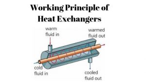
- Hot Fluid: The fluid entering the exchanger at a higher temperature.
- Cold Fluid: The fluid entering the exchanger at a lower temperature, intended to be heated.
The separation barrier (often metal plates or tubes) prevents the fluids from mixing while allowing the heat transfer to occur via conduction through the wall and convection from the fluids to the wall.
Key Factors Governing Heat Transfer
The rate of heat transfer ($Q$) within the exchanger is dictated by three primary factors, summarized by the following relationship:
$$Q = U \cdot A \cdot \Delta T_{lm}$$
- Overall Heat Transfer Coefficient ($U$): This represents how effectively heat is transferred through the wall and the fluid boundary layers. It accounts for conduction, convection, and crucially, the resistance caused by fouling (deposits on the surfaces).
- Heat Transfer Area ($A$): The total surface area available for exchange. Designers maximize this area through numerous tubes or plates to increase efficiency.
- Logarithmic Mean Temperature Difference ($\Delta T_{lm}$): This is the effective average temperature driving force between the two fluids across the length of the exchanger.
Flow Arrangements: Directing the Energy
The configuration in which the two fluids flow relative to each other significantly impacts the efficiency and the $\Delta T_{lm}$. The three most common flow arrangements are:
- Parallel Flow: Both hot and cold fluids enter the exchanger at the same end and flow in the same direction. The maximum temperature difference occurs at the inlet, decreasing steadily toward the outlet.
- Counter-Flow: The fluids enter the exchanger at opposite ends and flow in opposite directions. This arrangement maintains a relatively constant and high $\Delta T_{lm}$ across the entire length, making it the most efficient configuration.
- Cross-Flow: One fluid flows perpendicular to the other (e.g., in a car radiator).
Common Heat Exchanger Types
While the fundamental principle remains the same, the construction varies to suit different applications:
- Shell and Tube: Consists of a bundle of tubes housed within a large shell. One fluid flows through the tubes, and the other flows outside the tubes, through the shell.
- Plate Heat Exchangers (PHE): Uses a series of thin, closely spaced plates pressed together. The fluids flow in alternate channels, offering a large surface area in a compact space and high efficiency.
- Regenerators: Stores heat from the hot fluid in a matrix (often ceramic) and then releases it back to the cold fluid in an alternating cycle.
Understanding the principles of heat flow and flow arrangement is essential for selecting, sizing, and operating a heat exchanger to achieve optimal thermal performance and energy savings in any industrial process.
