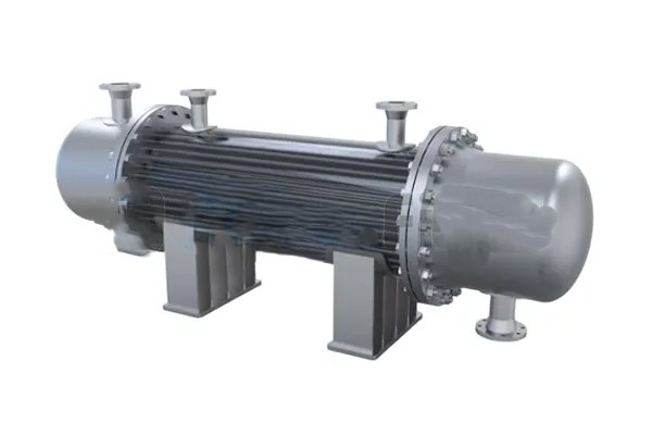
Counterflow Regenerative Exchangers represent an advanced evolution in heat exchange technology, merging two powerful principles: regeneration and countercurrent flow. These devices are built to conserve thermal energy by temporarily storing heat from a hot fluid and transferring it to a cold fluid that flows in the opposite direction.
In today’s world, where energy conservation, carbon reduction, and cost efficiency are top priorities, counterflow regenerative exchangers are becoming essential in industrial furnaces, gas turbines, chemical reactors, and HVAC systems. They significantly reduce the thermal energy loss, offering over 90% efficiency in certain designs.
Working Principle: How Counterflow Regenerative Exchangers Operate
Core Concepts:
- Regenerative Mechanism:
The exchanger doesn’t transfer heat through a solid wall (like a shell and tube exchanger). Instead, it uses a thermal storage matrix (such as ceramic bricks, metal mesh, or packed beds) to absorb and release heat between alternating fluid flows. - Counterflow Pattern:
The fluids (hot and cold) move in opposite directions, allowing the cold fluid to gradually meet increasing temperatures and the hot fluid to encounter increasingly cooler sections. This achieves a near-maximal temperature gradient, which is the most efficient configuration for thermal transfer.
Operation Cycle (in Two Phases or Continuously):
- Hot Phase:
The hot gas or fluid flows through the matrix and heats it up, depositing its thermal energy. This raises the temperature of the matrix material. - Cold Phase:
The flow is reversed or redirected (depending on design), and now the cold fluid passes through the already heated matrix, absorbing stored heat. - Repetition:
These cycles alternate or rotate continuously (especially in rotary regenerators), maintaining thermal equilibrium with very little energy loss.
Unique Design Types
Rotary Regenerative Exchangers
A rotating disc or drum holds the thermal matrix. As the drum spins slowly, hot and cold fluids flow through separate sections in opposite directions. The rotation recycles heat continuously.
Fixed-Bed (Cyclic) Regenerative Exchangers
Two (or more) chambers filled with matrix material alternate between hot and cold flow phases. Dampers or valves switch the direction of fluid flow.
Limitations & Design Considerations
While they are superior in many aspects, there are challenges:
- Complex Flow Switching Mechanism
For fixed-bed designs, valve or damper timing must be precise. - Thermal Leakage Risk
If insulation isn’t top-tier, stored heat may escape, reducing efficiency. - Cross-Contamination
If both fluids are gases, some backmixing may occur depending on sealing quality—unsuitable for sterile processes. - Initial Cost & Engineering
Higher upfront cost and design complexity due to moving parts (in rotary) or cycling (in fixed-bed).
Real-World Examples
- Regenerative Air Preheaters in Thermal Power Stations:
The Ljungström-type rotary preheater is a regenerative counterflow heat exchanger used in coal-fired boilers. - Tesla Gigafactory’s HVAC System:
Uses advanced counterflow rotary regenerators to recycle waste heat and reduce energy consumption in clean rooms. - Siemens Gas Turbines:
Incorporate ceramic regenerative exchangers in their microturbines for enhanced fuel-to-power efficiency.
As industries push toward net-zero carbon emissions and sustainable energy consumption, counterflow regenerative exchangers provide a high-performance solution for thermal energy reuse. Their ability to store and transfer heat cyclically or continuously with near-maximal efficiency makes them a vital component in modern engineering—especially where high temperatures and large energy flows are involved.
While they require precise engineering and flow control, the energy savings, performance stability, and environmental benefits make them not just viable but vital for the future of process industries, HVAC systems, and power generation plants.

