Introduction
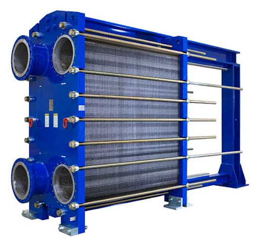
Plate and frame heat exchangers is a highly efficient and compact type of heat exchanger. It consists of multiple thin metal plates stacked together, creating channels through which fluids flow. These plates are clamped inside a rigid frame using tightening bolts. Gaskets are placed between plates to seal and control the flow of the fluids. This type of exchanger works on the principle of indirect heat transfer, meaning the two fluids do not mix but exchange heat through the plate walls.
Construction Details
- Plates
- The plates are typically made of stainless steel, titanium, or other corrosion-resistant materials.
- They are corrugated or patterned to increase surface area and induce turbulence, enhancing heat transfer.
- The surface area of each plate is engineered to ensure maximum efficiency within minimal space.
- Gaskets
- Gaskets are rubber seals placed around each plate.
- They serve two purposes:
- Prevent leakage of fluids.
- Direct the flow path so that fluids alternate between adjacent channels.
- Common gasket materials: EPDM, Nitrile, Viton, depending on temperature and chemical compatibility.
- Frame
- A sturdy carbon steel or stainless steel frame holds all the plates tightly together.
- Includes:
- Fixed frame plate (stationary side)
- Movable pressure plate (can be loosened to remove plates)
- Tightening bolts to compress the stack
- Guide bars to keep plates aligned
- Nozzles/Inlets & Outlets
- These are where fluids enter and exit.
- One set of ports for hot fluid, and another for cold fluid.
- Typically found in the frame’s fixed and movable ends.
Working Principle (Step-by-Step)
- Fluid Inlets: Two different fluids (one hot, one cold) enter the heat exchanger through separate ports.
- Flow Pattern: The design alternates flow between adjacent plates, so one plate side carries hot fluid and the other cold.
- Heat Transfer: As the fluids pass across the plates in opposite directions (counterflow), heat transfers from the hotter fluid to the colder one through the thin metal plates.
- Fluid Outlets: Both fluids exit at different ports after transferring heat.
Counterflow configuration is usually used because it maximizes the temperature difference across the exchanger, increasing efficiency.
Limitations of Plate and Frame Heat Exchangers
Not Ideal for High-Pressure/High-Temperature Applications
Why This Happens:
- Plate and frame heat exchangers are mechanically clamped with elastomeric gaskets between the plates. At high temperatures, these gaskets may soften or deform, and under high pressure, the sealing pressure may be exceeded, leading to leaks or even mechanical failure.
- The thin metal plates themselves (typically 0.3–0.6 mm thick) may warp or fatigue if pressure exceeds design limits.
Typical Limits:
- Temperature: Up to ~180°C (with special gaskets, up to ~200°C).
- Pressure: Typically up to 25 bar, though some units are designed for more with reinforced frames.
Solutions:
- Use welded plate heat exchangers or brazed plate exchangers (which do not use gaskets).
- Choose high-grade gasket materials like Viton or PTFE for better resistance.
- Implement pressure relief valves and temperature control systems.
Gasket Degradation
Why This Happens:
- Gaskets are made from materials like EPDM, Nitrile (NBR), Viton, or Silicone, each with specific chemical and thermal tolerances.
- Over time, exposure to harsh chemicals, UV radiation, ozone, or temperature cycling causes hardening, cracking, swelling, or loss of elasticity.
Contributing Factors:
- Exposure to incompatible process fluids (e.g., solvents, strong acids, oxidizers).
- Operation above the gasket’s rated temperature or pressure.
- Long operation cycles without scheduled maintenance.
Solutions:
- Select chemically compatible gaskets during design.
- Establish a routine maintenance schedule for visual inspection and replacement.
- Consider non-gasketed alternatives (like laser-welded PHEs) for aggressive environments.
Risk of Fouling with Dirty Fluids
Why This Happens:
- Plate channels are narrow and turbulent by design, optimizing heat transfer but making them prone to clogging when dealing with:
- Particulate-laden fluids
- Fibrous materials
- Scaling fluids (hard water, chemical precipitates)
- Dead spots or reduced turbulence caused by buildup reduce efficiency drastically.
Implications:
- Reduced heat transfer performance.
- Increased pressure drop.
- More frequent shutdowns for cleaning.
Solutions:
- Install pre-filters or cyclone separators upstream.
- Use anti-fouling chemicals or water softeners if applicable.
- Choose wider gap plates or alternate technologies for dirty applications.
- Schedule CIP (Clean-In-Place) or manual cleaning regularly.
Conclusion
Plate and frame heat exchangers are known for their high thermal efficiency, compact design, and easy maintenance, they do come with certain limitations that must be carefully considered during selection and operation. Their performance is heavily dependent on the integrity of gaskets, making them less suitable for high-pressure or high-temperature environments, and they are not ideal for handling dirty or particle-laden fluids without proper filtration. Additionally, the potential for gasket degradation, leaks, and fouling requires proactive maintenance and monitoring. Despite the relatively higher initial investment, these systems often provide significant long-term savings through energy efficiency and reduced maintenance downtime.